The Eye Beguiled
5. A gallery of impossible objects
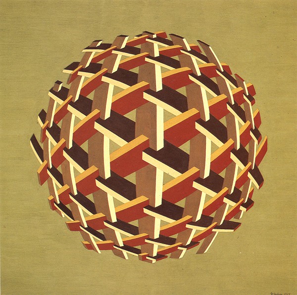
Figure 1. Hermann Paulsen, "Magic knot 1", gouache, 75x75 cm, 1985.
The spatial depth suggested by the cubic structure of this sphere is merely an illusion.
In 1985, while Zenon Kulpa was working on an article on the categorization of impossible objects, Putting order in the impossible, I sent him a few new ones. His reaction was:
"The more impossible objects are discovered, the harder it becomes to organize them into a rationally useful system."
Kulpa begins by dividing all two-dimensional objects permitting or suggesting a three-dimensional interpretation into four categories:
- Possible objects. These are perceived by the EYE as possible representations of 3-D objects; upon further appraisement, our faculty of reason also judges such objects to be realizable in three dimensions.
-
Probable objects. The EYE calculates a possible and matching 3-D object;
upon closer scrutiny, however, it becomes clear that the object cannot be
realized in three dimensions. An example is the truncated pyramid shown below
(fig. 3). Our EYE tells us immediately that this is a truncated pyramid,
although it can be easily demonstrated why such an object is impossible:
its three planes, when continued upwards, do not meet at a common apex.
Even after recognizing the rational truth of the situation, however, we cannot persuade our EYE to see something impossible, and for this reason the pyramid cannot be called an impossible object; if you refer back to my definition at the end of the previous chapter, you will see that it must be the EYE which decides whether an object - however impossible in reality - should indeed be assigned to the category of "impossible objects". - Improbable objects. The EYE's initial reaction is - impossible! But as soon as the possibility of spatial realization proffers itself from another angle, the EYE reacts by constructing an acceptable result. This is the case, for example, with the small block shown in Figure 4. If we tell our EYE that a small section has been cut out of the edge at a slant, it will accept this information and resume normal operation, particularly if we can also show it a three-dimensional model of this "impossible" block.
- Impossible objects. The EYE immediately identifies the spatial contradictions inherent in the figure; these are only later confirmed by rational assessment. Both the EYE and the reason judge the object to be impossible. In this case it is a true impossible object. These thoughts lead us to the question: is there any kind of objective yardstick which we can apply to tell us whether an object is impossible? Various experiments have been carried out in an attempt to establish, on a purely mathematical basis, criteria which might allow impossible objects to be defined and categorized. It is no surprise that they failed. For here, too, the EYE plays a dominant role - and the mechanisms of the EYE, developed over the course of evolution in order to guarantee the greatest possible chances of survival, by no means operate along simple mathematical lines.
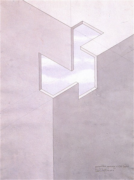
Figure 2. Oscar Reutersvärd, "Perspective japonaise n° 274 badhk", coloured ink drawing, 75x55 cm
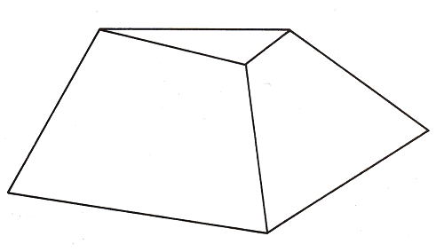
Figure 3.

Figure 4.
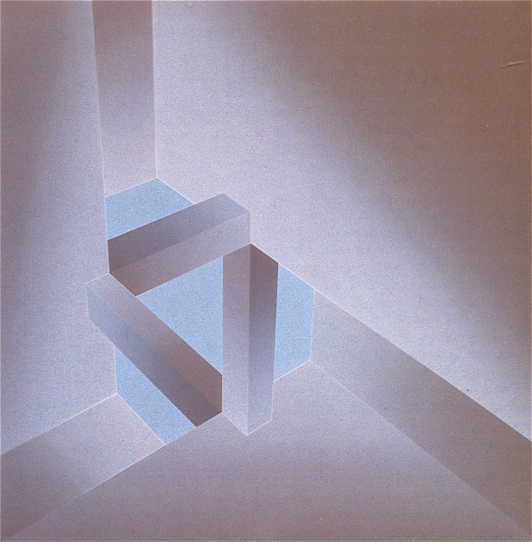
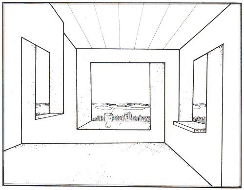
Figure 5. Dirk Huizer, "Looking in - Looking out", irisated screenprint, 49x49 cm, 1983
By acquainting ourselves more thoroughly with the "decision-making processes" of the EYE, we will be in a better position to discuss the topic with others. Let us therefore try the following useful exercise:
Imagine a horizontal plane S slicing through an object, as in the case of the impossible triangle shown in Figure 6a. Cover the half of the object below the line with a piece of paper, and then draw the cross-section of the upper half of the figure at S. Now cover the top half of the object, and draw the cross-section of its lower half at S. If your sketches differ in any way, you are dealing with an impossible object. In such cases, the EYE has clearly composed an object from parts which are mutually exclusive as soon as they are combined.
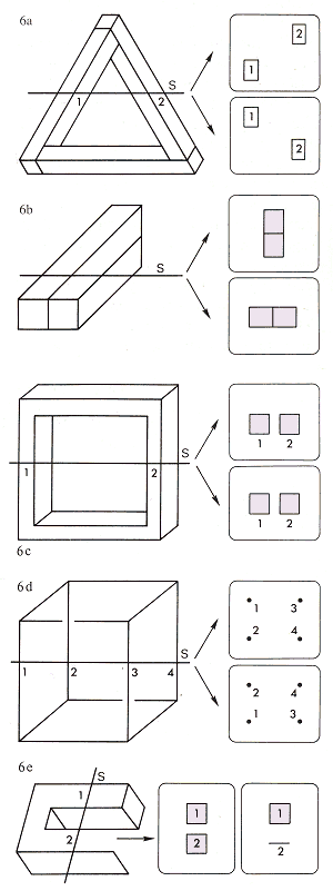
Figure 6.
In order to demonstrate the usefulness of this method as a means of detecting non-matching - and hence impossible - cross-sections, a few more examples are included here: Ernst's two-bar (fig. 6b), a normal four-bar (fig. 6c), an impossible cube (fig. 6d) and an impossible tuning fork (fig. 6e). The method proves less successful in the case of probable objects; if you apply the experiment to the truncated pyramid of Figure 3, for example, you will obtain corresponding cross-sections!
Meanwhile, we have still come no closer to creating specific categories of "real" impossible objects. Zenon Kulpa reaches no conclusions; he is obliged to make do with overlapping categories compiled ad hoc from a jumbled mixture of criteria. Only the categories "Multi-plane" and "Objects with parallel bars" offer useful subdivisions.
We, too, will be avoiding specific classifications in this chapter. We shall offer no more than a very incomplete overview, in which our grouping of objects makes no claim to be definitive. Our aim thereby is simply to trace a clear and logical path through our subject.
Apparent filling of space with impossible tri-bars
At first sight, Reutersvärd's composition on figure 23 of the previous chapter bears a number of similarities to Escher's Cubic division of space from the year 1952. But Reutersvard's work in fact represents a network of impossible tri-bars in which the large cubes hang like a curtain in the foreground, unconnected to the cubes in the second row. These may thus be seen as a second curtain behind the first, followed in turn by a third curtain of even smaller cubes.
Hermann Paulsen uses closed, curving tri-bars (fig. 1) to suggest the filling of a spherical volume. The reduction in size of the impossible tri-bars towards the edge of the circle is cleverly achieved!
Overlapping planes
We have already observed that the spatial contradictions within an impossible tri-bar can be traced back to a fundamental principle of stereometry, namely that three non-parallel planes intersect at a single point. In the drawing by Oscar Reutersvärd (fig. 2) we see three such planes appearing to form a corner of a rectangular volume. But if we extend these planes across the opening which interrupts them, we find that they intersect at different points. This inconsistency goes unnoticed precisely because pieces have been sawn out of the comers of the planes. The opening thereby created is itself an impossible object. The six planes in Huizer's picture (fig. 5) pose no problem in themselves. Their spatial arrangement is only rendered impossible by the tri-bar by which three of them are connected. Despite its apparently simple composition, the picture offers an unfathomably mysterious glimpse of illusory space.
Mono-bars, two-bars, and something in between
One might ask whether such a thing as an impossible monobar can exist at all. Figure 8 shows a normal bar at the top, followed by a bar with both sawn-off ends visible and, at the bottom, a bar with neither of its sawn-off ends visible. These last two are naturally impossible, but the EYE is determined to see them as bars with their ends sawn off at a slant; therefore, according to our earlier classification, they are not impossible objects!

Figure 7. Bruno Ernst, "Impossible penetrations", 1984
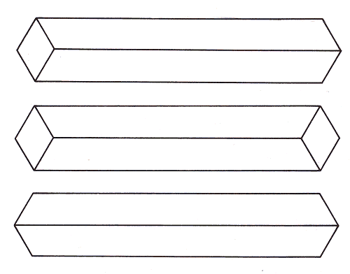
Figure 8.
In his drawing Gateway to the fourth dimension, (fig. 12), Sandro del Prete nevertheless finds a way of making such bars into impossible objects by adding a number of spatial details. All four bars run away from us; of all the objects visible in the picture, the figure of the woman is the closest. The bars share another curious characteristic: each plane is simultaneously both horizontal and vertical, depending on the side from which it is seen first. This peculiarity is emphasized by the inscriptions on the bars.
In Figure 7, an otherwise entirely normal bar has been rendered impossible by its setting: it passes between two other bars which in fact allow it no room to do so, since their edges are hermetically sealed along one side.

Figure 9. Zenon Kulpa, "2 1/2-dimensional beam, or 1:2", 1984
The object in Figure 9 was invented by Zenon Kulpa. At first glance we seem to see two parallel bars - only to lose the right-hand bar as it melts into the shadow of its neighbour. Perhaps this is best described as an impossible one-and-a-half bar!
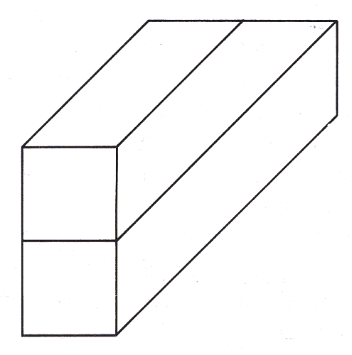
Figure 10. Bruno Ernst, "Impossible two-bar"
In the case of Ernst's impossible two-bar (fig. 10), the middle "rectangle" reveals a dual orientation: it appears vertical at the front and horizontal at the rear. Its interpretation is determined by the spatial information provided in the immediate vicinity of the outer ends of the two-bar.
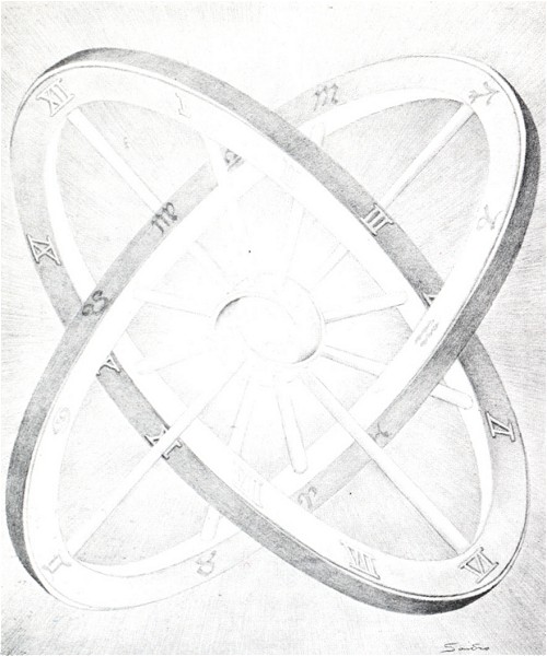
Figure 11. Sandro de1Prete, "Cosmic wheels", pencil drawing
Sandro del Prete's Cosmic wheels (fig. 11) can also be seen as an impossible (curved) two-bar. It bears resemblances to Escher's Cube with magic bands (fig. l6).
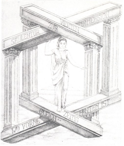
Figure 12. Sandro del Prete, "Gateway to the fourth dimension", pencil drawing
Impossible rooms
I drew Fifty Years Impossible Figures (fig. 13) as a jubilee poster for Oscar Reutersvärd. The opening in the upper corner of the room is impossible, because the three planes (the two walls and the ceiling) do not meet at a single point. Reutersvärd's first impossible object, an impossible tri-bar composed of nine cubes, appears as a heavenly body in the background. When Jos de Mey saw the poster, he drew his own - to my mind, typically "Flemish" - version of the composition as a Christmas card (fig. 14). Reutersvärd's original tri-bar is replaced by a star made up of two interwoven impossible tri-bars, and the picture is shown in centralized rather than false perspective.
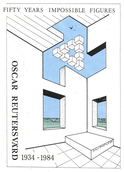
Figure 13. Bruno Ernst, poster design, 1984
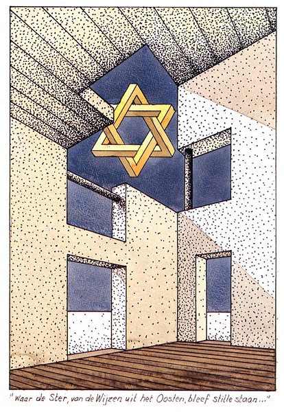
Figure 14. Jos de Mey (after Bruno Ernst), coloured ink drawing, 27x19.5 cm, 1985
The Strange rooms of Figures l5 and 16 are again based on the fact that three planes intersect at more than one point. In both pictures this produces side walls which simultaneously face towards us. In Figure 15, moreover, one of the solid walls vanishes into thin air, although the illusion of a room nevertheless remains perfectly convincing.
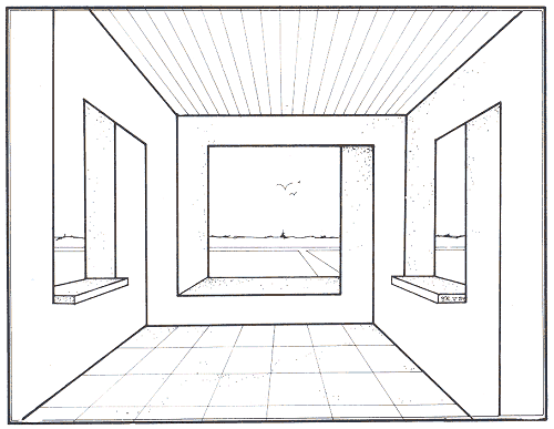
Figures 15 and 16. Bruno Ernst, "Strange rooms"
Tri-bars: alone and in relation to their surroundings
An impossible tri-bar can serve as the subject of a picture without further accessories, as can be judged from Dirk Huizer's screenprint (fig. 17).
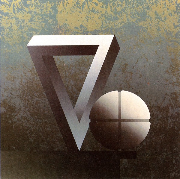
Figure 17. Dirk Huizer, "Penrose triangle and imperial orb", irisated screenprint, 45x45 cm, 1984
In Figures 18-20, on the other hand, the environment within which the tri-bar appears plays an important role. Figure 18 shows an impossible tri-bar standing in the hall of my apartment. Reutersvard promptly responded to this drawing with an interesting variation (fig. 19), in which the tip of the tri-bar is partially obscured by a ceiling support, thereby also altering the line of shadow it casts. Inspired by this, I then drew Figure 20; I added a few more impossibilities to the room, which had now developed into a museum gallery with impossible objects hanging on its walls. But there were clearly serious difficulties involved in exhibiting a "real impossible tri-bar".
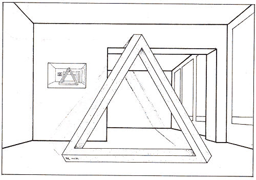
Figure 18. Bruno Ernst
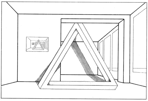
Figure 19. Ernst/Reutersvard
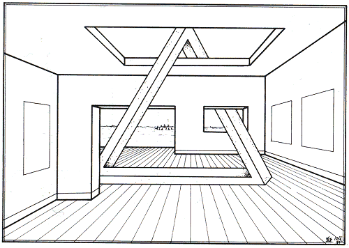
Figure 20. Bruno Ernst
Figure 21 shows a variation upon the usual impossible tri-bar, in a setting borrowed from a drawing by Macaulay. It now shows the Moon in the year 2034, where the finishing touches are being put to a monument celebrating 100 years of impossible tri-bars.

Figure 21. Ernst/Macaulay
Impossible multi-bars
Figure 22 represents a solid frame which is above and to the left of our viewpoint. From this angle each comer is seen differently, as if one of four distinct comer types which can be numbered 1-4.
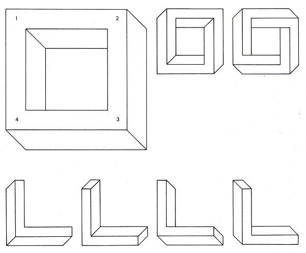
Figure 22.
The frame as a whole can thus be described as (1234). By employing these individual corners in different combinations, we can build frames in which the EYE will discover contradictory spatial data. The two drawings to the right of Figure 22 show two impossible four-bars of this type. One has a corner combination of (4444) and the other, (4141).
Using the same principle, it is not difficult to combine more than four bars into an impossible figure.
It is interesting to note, however, that multi-bars produced in this way are less tantalizing as impossible objects than impossible tri-bars and four-bars. First, the suggestion of right angles in an impossible object, e. g. through a perpendicular combination of bars, gives the EYE a useful reference point from which to determine directions in space, and any contradictions will thereby be made more apparent. The arms of a multi-bar, however, always meet at an angle that is greater than 90°; spatial directions are therefore harder to determine. Secondly, the more bars and lines that there are in a structure, the less its contradictions will strike the eye. Multi-bars, however, are very simple in design. In Figure 23 we see one five-bar (13143), one six-bar (444444), and the curved two-bar (44) which we met earlier in Figure 11.
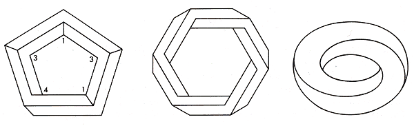
Figure 23.
Four-bars
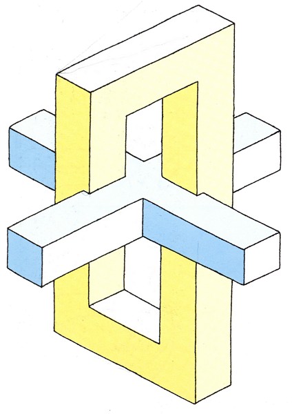
Figure 24. Oscar Reutersvärd, coloured ink drawing, 57x76 cm
The four-bar in its classic form is shown in Figure 31. It belongs to the (3441) type, and its building-block composition lends it a particularly realistic character. The surface area and volume can again be calculated: 76 dm2 and 19 dm3. We can experiment with this figure just as with the impossible tri-bar in Chapter 4. Meanwhile, Figure 30 gives you all the parts you need to build an impossible four-bar; you simply have to screw them all together!
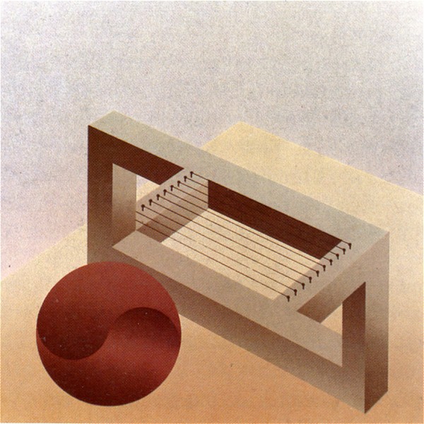
Figure 25. Dirk Huizer, "Still life no. 3", irisated screenprint, 44x44 cm, 1983
The combination of an impossible four-bar with a normal four-armed cross highlights the fact that the top and bottom bars appear perpendicular to one another (fig. 24). Dirk Huizer's impossible stringed instrument (fig. 25) is made up of impossible tri-bars and four-bars, and a normal four-bar.

Figure 26. Diego Uribe
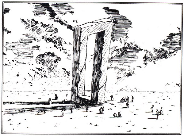
Figure 27. Macaulay/Ernst, "Megalithic monument", ink drawing
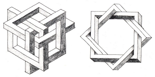
Figure 28. Dirk Huizer, small sketches from his correspondence with the author
A four-bar can also serve happily as a megalithic monument (fig. 27); the setting is again borrowed from a drawing by Macaulay. Everyday objects can further be combined into impossible objects by overlapping them in impossible ways (figs. 26 and 28).
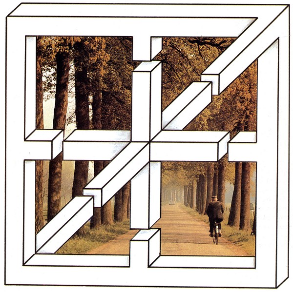
Figure 29. Bruno Ernst, Collage, 1984
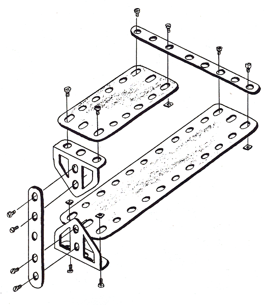
Figure 30. Govert Schilling, ink drawing, 1984
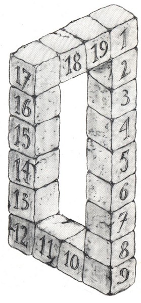
Figure 31. Bruno Ernst, impossible four-bars
Multi-bars as jigsaws
Various jigsaws have been designed whose pieces allow the player to make up every possible and impossible type of tri-bar, four-bar, etc. The most obvious method is for the puzzle pieces to illustrate all the possible corner shapes in such a way that one bar of one hexagon always joins onto a bar of another hexagon.
Diego Uribe has designed a much more sophisticated solution, opening up many more possibilities with much less effort. He uses not complete corner shapes, but bar elements instead, which he places along the edges of equilateral triangles. It is possible to make up every possible multi-bar with just thirty-two different triangles (fig. 32), including not only the multi-bars we have already seen, but also figures in which more than two bars meet at one comer, such as in impossible cuboids. There is but one limitation: only perpendicular relationships are possible between the bars within an object. Figure 33 shows you how to combine the pieces into an impossible four-bar, while Figure 34 shows a more complex form in which three bars meet at one comer.
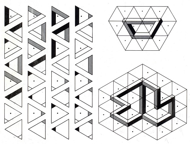
Figures 32, 33 and 34. Diego Uribe, design for jigsaw puzzle; the individual pieces (left) and two figures made from them (right)
Cuboids
Escher was the first to draw an impossible cuboid (cf. Chapter 6). As in the case of multi-bars, a wide range of rather different cuboids can be composed using the corner types of the - normal - original (of. fig. 35). Figures 36 to 42 show a selection of variations on the theme of impossible cuboids.
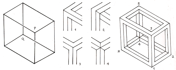
Figure 35. The individual corners (centre) of a normal cuboid (right) can be combined into impossible objects (below).
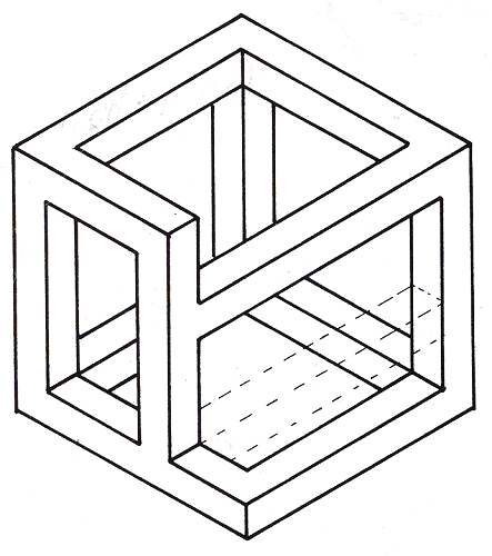
Figure 36
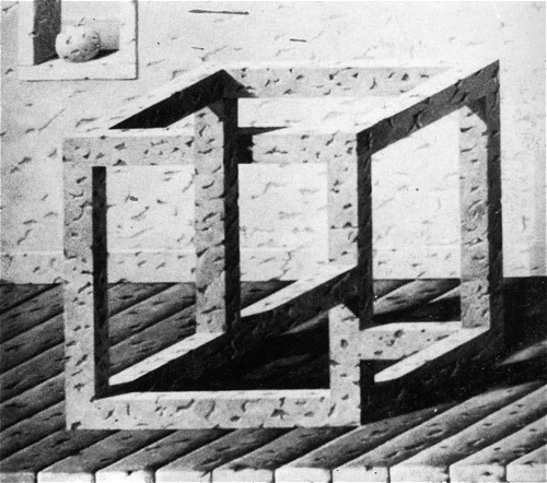
Figure 37. Jos de Mey
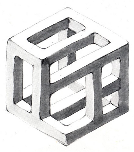
Figure 38.
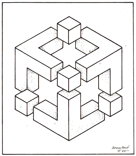
Figure 39.
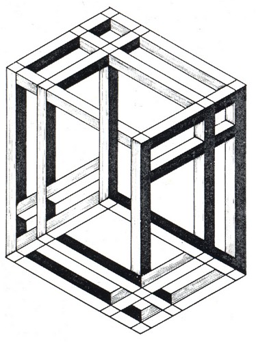
Figure 40. Michael Jedrzejewski, "Cube", 1985
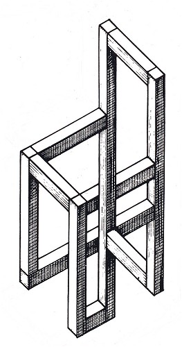
Figure 41. Michael Jedrzejewski, "Chair", 1985
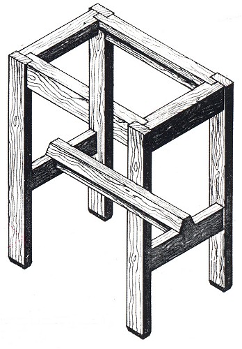
Figure 42. Michael Jedrzejewski, "Table", 1984
Steps and chessboards

Figure 43. Bruno Ernst, "Steps or floor tiles", 1984
If we walk through the centre of the - in actual fact, impossible - doorway in Figure 43, we remain on the same horizontal plane, standing on a tiled floor. If we look left, however, our path seems to lead up some steps.
We see the same effect in the photograph of the chessboard (fig. 44). If we move from the White Knight via the Castle to the King, we stay on the same level. In moving directly from the White Knight to the King, however, we gain the impression that the King is standing on a higher level than the Knight. In reality everything is flat!
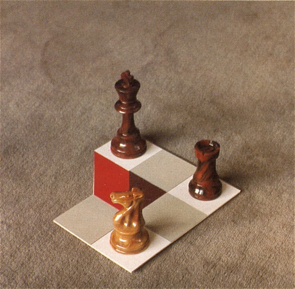
Figure 44. Bruno Ernst, "Chessboard I", 1985
A number of impossibilities have been incorporated into Figure 45, a screenprint by Fred van Houten. Take the ladder, for example: it starts against the wall - and ends beside it. Escher makes similar use of a ladder in his Belvedere (Chapter 6, fig. 18).
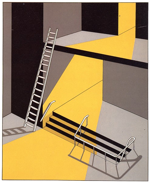
Figure 45. Fred Van Houten, "Steps", screenprint, 30x24 cm, 1984
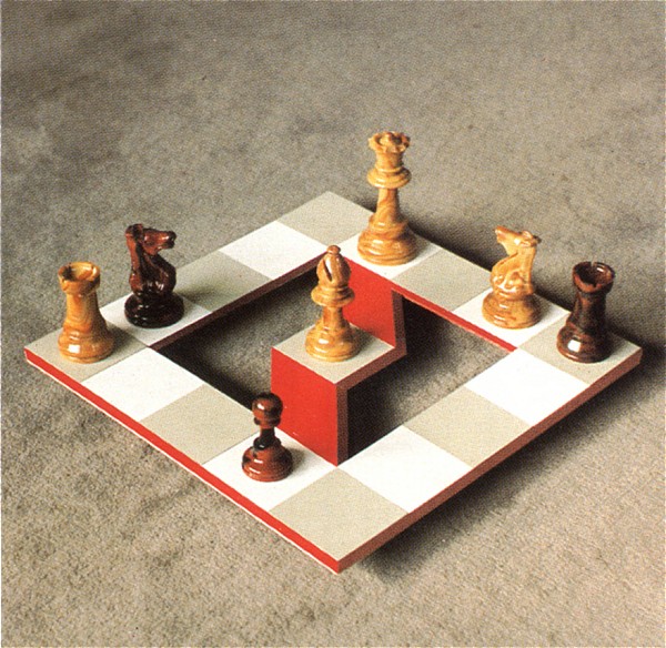
Figure 46. Bruno Ernst, "Diagonal", photograph, 1985

Figure 47. Bruno Ernst, "Spiral", photograph, 1985
Multiple planes
A multiple plane looks like a single, flat plane when viewed from one point in a drawing, and yet appears to consist of two or more planes when seen from another point in the same drawing. This is the oldest type of impossible object; as we shall see in the next chapter, it appears - unintentionally or unconsciously - in works by much earlier artists. Figure 48 demonstrates how a multiple plane can be created. At the top, we see an archway standing on a tiled floor. Consulting the plan of this floor reproduced in the bottom left-hand corner of this page, we see that the left-hand foot of the arch is standing on the black square, and the right-hand foot on the square marked number 2. Let us now redraw the same archway, but making its right-hand side slightly shorter so that it ends on square 3. We have immediately created an impossible object: the seemingly flat front view of the archway contains two base lines, a and b - and that is impossible. We can continue to shorten the right-hand side until it reaches square 5. The archway has now become part of an impossible four-bar, here achieved by a different method than that described earlier. In the drawing by Jos de Mey (fig. 49), the upper section of the wall forms just a single plane with three diamond-shaped openings. At ground level, however, the same plane multiplies into four walls at varying distances from the viewer, at the same time enclosing a relatively large space, almost as if it were a roofed pergola.
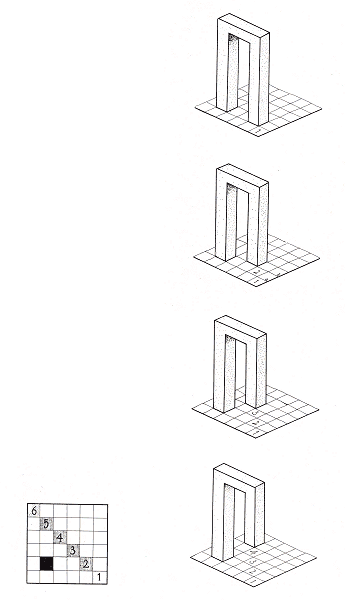
Figure 48.
In Figure 50 we see how the side plane of a cube can duplicate itself to make room for ever smaller cubes.
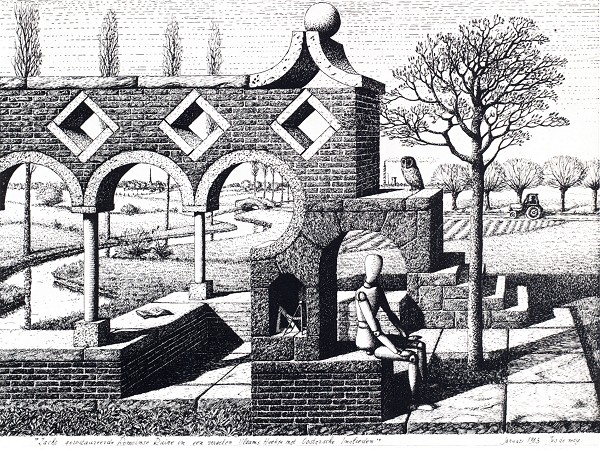
Figure 49. Jos de Mey, "Carefully-restored Roman ruin in a forgotten Flemish locality with Oriental influences", ink drawing, 30x40 cm, 1983
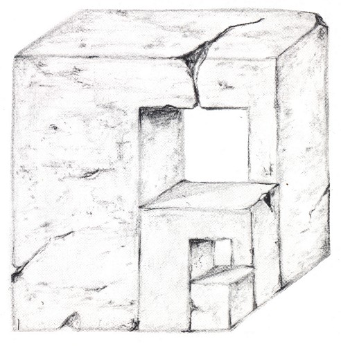
Figure 50. Bruno Ernst, "Nest of impossible cubes", 1984
Continuous steps
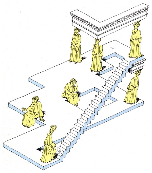
Figure 51. Reutersvärd/Ernst, "Caryatids"
When looking at a flight of steps, we first decide in which direction we wish to follow it. Having chosen our direction, further spatial clues will then enable us to judge whether the stairs lead up or down. The direction of tread thereby plays no role (fig. 53). It is relatively easy to draw a set of steps which, having set off in one direction, rise or fall without end. The origin of the spatial confusion sown by the continuous steps on the left of Figure 52 is unmasked in the drawing of a normal staircase on the right. Figure 51 shows a continuous staircase by Reutersvärd, to which I have added figures emphasizing the impossibility of the situation.
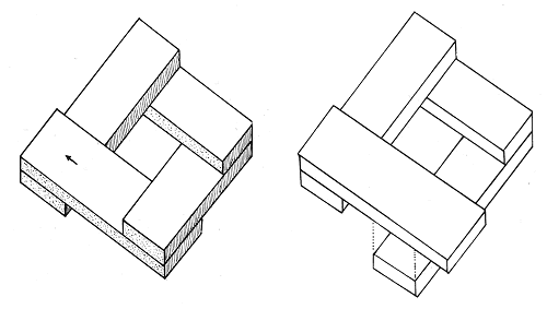
Figure 52.
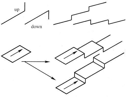
Figure 53.
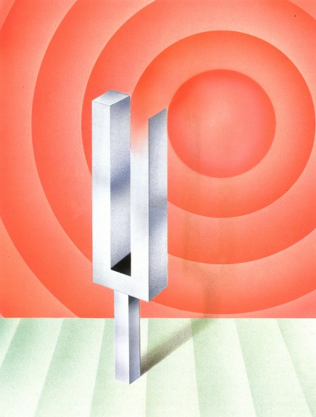
Figure 54. Bruno Ernst, "Negative sound", 1984
Planes with two orientations
The astonishing nature of this type of plane is illustrated by the following example: the small temple shown in Figure 55 can be mounted from the left in just two steps. Approached from the middle, however, there are three steps to ascend, and no less than five on the right. The steps leading up to the temple are in fact composed of three elongated "rectangles" aligned in two different directions. This has the effect of making the immediate surroundings appear as a vertical plane on the left and a horizontal plane on the right.
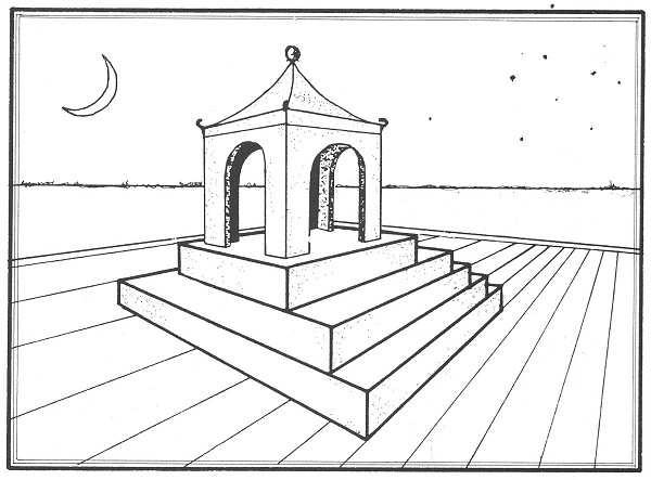
Figure 55. Bruno Ernst, "The wearisome and the easy way to the top", 1984
This type of plane is not warped, but the EYE calculates its orientation on the basis of details gathered from the immediate setting, and thus in two different ways. Similar planes occur in Reutersvärd's Layered blocks (fig. 56).
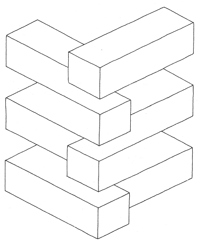
Figure 56. Oscar Reutersvard, "Layered blocks"
Penrose's circular staircase
In 1985 Roger Penrose designed a combination of five impossible cuboids; Figure 57 represents one of its variations. Flights of steps lead from one cube to the next, but if we set off on a circuit standing upright, we will regain our starting-point horizontal! Life returns to normal in a similar arrangement of six cubes, but the strange phenomenon reappears in the case of seven.
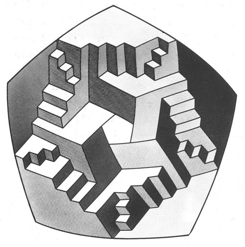
Figure 57. "Stair blocks", after Roger Penrose
From ambiguous figures to impossible objects
A rhombus such as Sandro del Prete's chessboard (fig. 59) is an ambiguous figure: it is a square seen from either above or below. The positioning of its chessmen and ladders creates an impossible "both/and" situation, however, with both "above" and "below" interpretations presented simultaneously and in mutual contradiction. The peculiarity of the situation becomes clear when we move the White Castle square by square "diagonally upwards" along the edge of board.
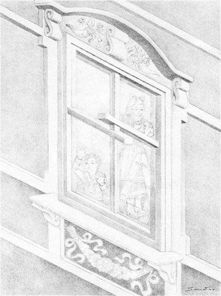
Figure 58. Sandro del Prete, "Children looking out of the window", pencil drawing
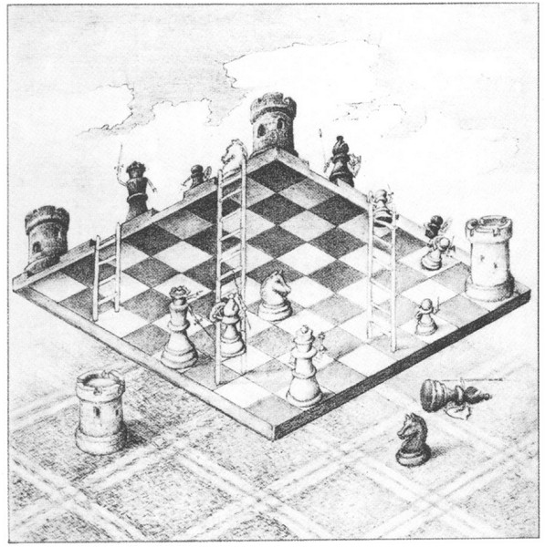
Figure 59. Sandro del Prete, "The inverted chessboard", pencil drawing
A similar example of the transformation of an ambiguous figure into an impossible object is seen in Figure 58. Taking the window frame on its own, it can be seen either as a window facing west viewed from above, or as a window facing south viewed from below. Both interpretations are reinforced by secondary spatial clues found in the decoration of the windowsill, the ornamentation over the top of the window and the two separate halves of the window cross. The two incompatible view-points are fused by the figures we see inside the house: we are able to perceive the entire composition at once and both from above and below.
Boundary conflicts
We offer three examples of a type of impossible object in which matter appears to vanish into thin air, the so-ñalled "devil's fork" type.
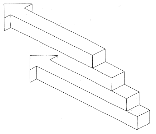
Figure 60. Oscar Reutersvard, "Two arrows"
The tuning fork in Figure 54 in fact has only one solid arm; the sound waves are therefore shown as if issuing from the shadow of this impossible object. Some of the arms of the candlestick in Figure 61 similarly appear not to exist. And it is impossible for Reutersvärd's two arrows (fig. 60) to have four ends. Yet how many bars does it truly contain - two, or three? On no account four!
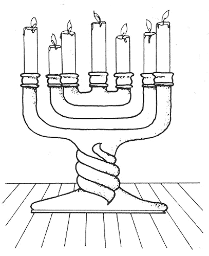
Figure 61. Bruno Ernst, "False candles", 1984