A set of impossible tiles
Printed in
THE THIRD INTERNATIONAL CONFERENCE
MATHEMATICS & DESIGN 2001
DEAKIN UNIVERSITY
GEELONG, AUSTRALIA
A SET OF IMPOSSIBLE TILES
Diego Uribe
Editorial Juegos, Argentina
Impossible figures (IF) are a part of our common visual language. This paper describes a set of tiles used to construct IF made of square-section bars intersecting at right angles - the type of IF including the "impossible triangle". The paper starts by presenting the generating method of the set of tiles. IF constructed with the tiles are then divided into three groups: IF with no bar crossings, IF with bar crossings, and IF with ambiguous point-of-view, corresponding to increasingly larger subsets of the complete set. The subset used to obtain IF with no bar crossings provides an elementary algorithm to recognize if a figure is impossible. The basic structure of IF used by Escher is then built with the tiles. Finally, the tiles are used as a creative aid, presenting examples of combinatorial puzzles, plane tessellations, IF fractals and sketching method to generate "real looking" IF. Thus, the set of tiles brings together in an intuitive way characteristics of IF usually studied by different disciplines, providing a link between mathematics, art and psychology.
Impossible figures
Since their use by Oscar Reutersvärd [1] and Maurits Cornelius Escher [2], impossible figures (IF) have become a part of our common visual language, with an extended gamut of artists working in the field.
IF made their début in a scientific journal in a paper by L.S. Penrose and R. Penrose [3]. The Penroses´ paper describes two IF: the tribar (also known as the impossible triangle) and the never-ending staircase. Both were based on the same deception, tricking the perception into believing that two points that coincide in the picture also coincide in three dimensions space. How this is achieved can readily be seen by considering a cubic grid and a closed circuit along some of its edges (fig. 1).
Figure 1. A cubic grid and a closed circuit along some of its
edges.
Consider the point in the illustration where the path intersects itself, and the horizontal and vertical edges involved. Three possibilities arise: a. the vertical edge runs in front of the horizontal edge, b. the vertical and horizontal edges intersect, and c. the vertical edge runs behind the horizontal edge. Replacing the edges by square-section bars, a gives birth to a possible figure, while b and c generate impossible figures (fig. 2) [4].
Figure 2. Three interpretations of the path in figure 1 rendered as
square bars structures.
The generation of the set of tiles
If figure 2 is drawn using isometric perspective (fig. 3), a set of triangular tiles is suggested, with the edges of the grid being the edges of the tiles and defining orthogonal axis running in the three directions of space. A tile can be completely blank or have one or more coloured sides and/or corners, each coloured side or corner being a part of a square-section bar. Figures thus rendered are seen from above, with bars coloured as if illuminated from above-left, so that faces looking up receive full light (yellow), faces looking left are somewhat in shadow (blue) and faces looking right are in complete shadow (chocolate). (Although coloured faces are not mandatory, they ease figure interpretation.)
Figure 3. The three structures in figure 2 drawn in isometric perspective
suggest tiles.
The question is, of all the possible combinations of coloured sides and/or corners, which are necessary to produce impossible (or possible) figures of the type in figure 3? The answer relies on two factors - the type of figures we want to obtain and the concept of "fundamental tile".
Type is to be understood following figure 1. Consider again the point where the path intersects itself and the three interpretations in figure 2. A type will be defined by considering the vertical and horizontal bars at the crossing. If the bars cross at different levels, i.e. if one bar occludes the other, (fig. 2a & 2c) we define a type requiring a certain set of tiles; if they meet (fig. 2b), we define another type, requiring another set of tiles. This last set is a subset of the former [5, 6] and is presented in figure 4.
Figure 4. A set used to construct impossible - or possible -
structures made of square bars meeting at right angles. The structures obtained will have
no bars crossing (in the figure) at different levels. Duplicate tiles and
dots are usage aids and will be removed later.
In figure 4 tiles are grouped according to the quantity of coloured sides and/or corners: tiles with one, two or three coloured sides, with one, two or three coloured corners, and with one coloured edge and one coloured vertex. Some tiles are duplicated, once with a central dot and once without it. Neither the dot nor the duplication are necessary, but will be useful when constructing figures.
When point of view, shadowing and crossings are accounted for, tiles in this set represent all the available combinations of coloured sides and/or corners. For example, there are no tiles with a coloured side and corner belonging to the same tile edge, nor other six possible combinations for two coloured sides tiles, since these are only used when two bars cross each other.
Now for the "fundamental tiles" concept. Consider the central tile in figure 5a - it forces the appearance of a Penrose impossible triangle. But a similar triangle, although larger, can be obtained by using other tiles (fig. 5b).
Figure 5. A fundamental tile is one that cannot be replaced by a group of
other tiles. The central tile in a is not fundamental: it can be replaced by
the four central tiles in b. Again, the central tile with three coloured
corners in b is not fundamental.
Then, the central tile in figure 5a is not "fundamental", since it can be replaced by a group of other tiles with the same topological properties (notice that the central tile in the enlarged triangle is also non-fundamental). Following this concept, the only fundamental tiles in the set in figure 4 are those with one and two corners and with one and two sides. The selection of tiles for an actual game will be a compromise between the quantity of different designs and the total quantity of tiles.
Why triangles?
Although the triangular tiles appeared naturally as a consequence of the use of isometric perspective, it remains to be analysed the convenience of the triangular shape.
IF made with the set in figure 4 are constructed with two elements: bars and joints. As a consequence, two approaches are available when designing a set of tiles: bar-oriented or joint-oriented. In the bar-oriented approach the tiles represent a catalogue of bars (or parts of them) and joints are created by placing tiles side by side. In the joint-oriented approach the tiles simply represent the catalogue of joints. That is, the bar-oriented approach belongs to a more basic level than the joint-oriented. The present set of tiles clearly follows the baroriented approach: sides and/or corners represent bar faces. Here the triangle is the most economical available shape, since each one of its three sides follows one of the three different directions in space. In this sense, triangular tiles are a sort of fundamental particles or blocks upon which the figures are constructed and in the next section they will be used to derive a simple algorithm to test impossibility.
But the joint-oriented approach may have other desirable properties. It could be that the quantity of different joints is smaller than the quantity of fundamental triangular tiles. This is not the case. Consider a certain joint centred in an undefined plane-tiling polygon (fig. 6a). Notice that, due to the point of view and the colouring scheme of the bars, such joint exists in six different versions following orientation. When a complete catalogue of all possible joints (and their different orientations) obtainable with the set in figure 4 is considered (fig. 6b) it results in a larger number of tiles than the set itself: 64 joints against 34 tiles (24 if only fundamental tiles are considered). Hence, also in this sense the triangular shape is more economical. Similar results hold when a non-coloured version of the tiles, or the enlarged sets later in this paper, are considered.
Figure 6. a. A joint centred in an undefined plane-tiling polygon exists in
six versions, one for each orientation. b. A catalogue of all available
joints in which bars abut on a point. Following orientation, the first joint
of the first row and the last of the third row exist in 1 version each one.
The last joint of the second row exists in 2 versions. The last joint of the
first row and the first of the last row exist in 3 versions each one. All
the other joints exist in 6 versions each one, making a total of 64
different joints.
A simple algorithm to test impossibility
Suppose a triangular tessellation of the plane, painted like a chessboard. Refer to the tiles in figure 4. Tiles with a dot must be placed over black triangles, tiles with no dot over white. In both cases the colour (shadow) scheme must be preserved. Figures thus obtained can be open (fig. 7a) or closed (fig. 7b & 7c).
Figure 7. Three structures made with the set in figure 4: a is open
(has loose ends) and, like all open structures, possible; b is closed and
also possible; c is closed and impossible.
Take the path along the grid edges in the closed figures and consider it as a flight of stairs (fig. 8a & 8b). If the flight of stairs is possible, a walk along its length must climb as many steps as it descends. Otherwise, the flight will be impossible. In figure 8a the path climbs a step (the length of a tile side) at the right and descends it at the left; in figure 8b it climbs two steps but descends none. Hence, figure 7b is possible while 7c is impossible. A similar analysis can be made by considering the other two directions of space: in a possible figure the distance travelled in one sense along a certain direction must be travelled back in the opposite sense. Consider the tiles interior to the path. Climbs were made along the side of a non-dotted tile while descents were made along the side of a dotted one (the same holds for the other directions of space).
Figure 8. The path along the grid corresponding to figures 7b and 5c. If the
quantity of dotted tiles interior to the path equals the quantity of
non-dotted, the figure is impossible (a); else, is impossible (b).
Consider now the construction of a patch whose perimeter is a path similar to those in figure 8.
Figure 9. Three stages in the construction of a patch (see main text).
Start by placing, say, a dotted tile (fig 9a). If this tile constitutes the complete patch, the corresponding figure – once the tiles exterior to the path are placed - is impossible. To get a possible figure a non-dotted tile should be added to the interior patch (fig. 9b). If a new dotted tile is added to the patch, it will result again in an impossible figure (fig. 9c).
This construction can be carried on ad infinitum. Hence, to get a possible figure, the quantity of dotted and non-dotted tiles in the patch must be even. Consider now the perimeter of the patch (that is, the path in figure 9) measured in tile sides. Every time a dotted tile is placed, the quantity of dotted tiles in the patch is increased by one, while the difference between the quantity of dotted and non-dotted sides in its perimeter is increased by three. Moreover, each new side runs in a different direction in space. Then,
Td – Tn = (Pd – Pn)/3,
where Td and Tn are the total quantities of dotted and non-dotted tiles in the patch and Pd and Pn are the quantities of dotted and non-dotted tiles sides along its perimeter, with (Pd – Pn)/3 having the same value for each one of the three directions in space. This results in a simple rule: a closed figure made with the present subset is possible if its interior has equal quantities of dotted and non-dotted tiles. If the quantities differ, the figure is impossible, and the difference stands for the quantity of descended steps that are not climbed again.
The Penroses staircase
In a preceding section the figures constructed with the tiles were considered as a general staircase with steps in the three directions of space. Here the tiles will be used to construct a never-ending staircase (fig. 10). Figure 10a shows the skeleton of such a staircase. The difference between dotted and non-dotted tiles is eight, corresponding to the eight steps in the flight. Figure 10b shows the finished staircase, where each step was drawn by extending the edges of certain bars in the previous figure.
Figure 10. a. The skeleton of a never-ending staircase. b. The staircase
sketched upon the skeleton. This staircase is similar to the one by the
Penroses.
Crossing bars
The set in figure 11 is like the one in figure 4 with the following differences: 1. Dotted and non-fundamental tiles have been removed. 2. It was enlarged to include tiles necessary to construct bars crossing at different levels (group of six tiles at upper-right and lower-right). These tiles have a coloured corner that belongs to a bar that occludes another bar (upperright group) or occludes a joint (lower-right group).
The algorithm to test impossibility based on the difference between dotted and nondotted tiles is of limited use here: it tells whether two bar meet at a point but, if not, it does not tell which bar occludes the other. Moreover, the occluding scheme is dependent on the chosen point of view, while the algorithm is independent - if a vertical bar occludes a horizontal one when seen from the front, the horizontal bar will occlude the vertical one when seen from behind, while a joint remains a joint seen from anywhere. The failure of the algorithm can readily be seen in figure 12a: for the same crossing, the upper part of the figure has more dotted tiles, while the lower part has more non-dotted.
Figure 11. A set of tiles that allows bars crossings. The set in figure 4 is
a subset of the present after the dots and duplicated tiles are removed.
A classical method to check the occluding pattern is to place a coordinate system somewhere in the figure. If the system is selected so that the positive axes point towards the viewer (fig. 12b), points with higher coordinate values will occlude points with lower values. In figure 12c the point where the path crosses itself has coordinate 0, 3, 2 (measured in tiles units) if belonging to the vertical bar, and -2, 1, 0 if belonging to the horizontal. Hence, the vertical bar occludes the horizontal. Notice that the difference is the same for each of the three axes.
Figure 12. a. The algorithm based on the quantity of dotted and
non-dotted tiles cannot be used to tell which bar occludes the other: while
the upper part of the figure has more dotted tiles, the lower part has more
non-dotted. b. A coordinate system with the positive axes pointing towards
the viewer. c. The point with the higher coordinate values belongs to the
occluding bar. d. A simplified method. Starting at the crossing point and
travelling along vertical bars, the path goes 1 tile up and descends 3. The
negative value (-2) indicates the bar with the starting point occludes the
other.
This result was obtained when the figures were treated as general staircases and can be used to simplify the method. Select the point where the path crosses itself as origin. Select one of the two axes involved. Walk along the path considering only distances travelled along the chosen direction (with their corresponding sign). If the outcome is negative, the chosen axis occludes the other; if positive, the chosen axis is occluded (fig. 12d).
Escher´s Belvedere structure
The structure in figure 13 was made with the set in figure 11. Notice that the shadow scheme is preserved and that bar crossings always involves a tile with a coloured corner superposed over a coloured side. This structure is of special interest because it is topologically similar to the middle portion of the building in Escher´s Belvedere.
Figure 13. A figure made with the set in figure 11. Notice the impossible
overlapping of bars: horizontal bars at the top occlude columns that lie in
front at the bottom.
Compared with Waterfall and Ascending and Descending, Belvedere has a different point of view. While the former are seen from above - the impossible parts of the prints being in such sense literal renderings of the illustrations in the Penroses´ paper - the latter is seen from a point of view placed at the same level as the impossible part of the building.
Choosing this particular point of view allowed Escher to take care of the size difference between the left and right parts of figure 13 and to render it into a much more realistic looking structure (fig. 14). Of course, we are not implying Escher followed this line of thought, nor that he ever considered figure 13, but that the use of such a point of view is absolutely necessary to transform the dullness of this figure into the gracefulness of the Italian palazzo in the print. The Penroses´ paper had nothing of the sort.
Figure 14. The structure in figure 13 seen from a point of view halfway
between upper and lower horizontal bars. This structure is similar to the
one in Escher’s Belvedere.
Two simultaneous points of view
A new type of IF is now considered: figures with two simultaneous points of view. That is, a part of the structure is seen from above, while the rest is seen from below. A way of producing a suitable set is by starting with the set in figure 11 and adding mirror image copies of the tiles (fig. 15). (Tiles with bilateral symmetry are not copied since the mirror image is alike the tile itself.)
Figure 15. A set that can be used to produce figures with two different
points of view, so that parts of the figure are seen from above while other
parts are seen from below.
The colouring scheme of the structures made with this set depends on the axis linking the two parts of the figure with different points of view. In figure 16a the two parts are linked by a vertical axis, in figure 16b by a down-left to top-right axis, and in figure 16c by a top-left to down-right axis. In all three the colouring scheme is the same in the parts seen from above, while differs in the parts seen from below.
Once the link is chosen, the colour of the faces with the last orientation gets determined. As a result, other bars linking the two parts that run in a different direction involve a colouring contradiction - a bar coloured in one shade in a part of the figure may be coloured differently in another part of the figure (see vertical bars in fig. 16 b & 16c).
Use of the set of tiles
In this section some uses of the tiles will be presented. In order to save space, from here onwards non-fundamental tiles will also be used in the illustrations. Appealing IF. The more straightforward use of the set of tiles is to construct appealing IF. Figure 17 presents a knot, in some way reminiscent of the knots by Leonardo or of Celtic traditional ornaments. It is made of possible and impossible parts linked both in possible and impossible ways.
Figure 16. The colour scheme of the part seen from below in an IF
with ambiguous point of view depends on the direction of the edge linking it
to the part seen from above. a. The link is the vertical central bar. b. The
link is the bar running from down-left to top-right. c. The link is multiple:
the three parallel bars running from top-left to down-right.
Figure 17. A knot made with the set (many of the tiles used are
non-fundamental).
Fractals. As seen in a previous section, structures constructed with the set in figure 4 are unmistakably defined by a path along the edges of a cubic tessellation of space. If this path is closed and has no self-intersection, it can be used to define a regular general Koch island [7]. Figure 18a shows the initial polygon (a Penrose tribar) and the first generation of the fractal superimposed; figure 18b shows the fourth stage in the construction. Notice that both the initial polygon and the fractal are impossible. This is not always the case: an island constructed with a Koch curve (also known as the snowflake curve) starts with an IF that is transformed into possible at the first stage of the construction.
Figure 18. A regular fractal. a. The original polygon, an
impossible tribar, and the first generation superimposed. b. The fourth
generation.
Puzzles. Several combinatorial puzzles can be posed. For example, figure 19a shows an impossible triangle. The poser asks to use the tiles in this figure and rearrange them into a possible structure, preserving the overall shape of the patch (indicated with a bold line). Figure 19b shows one of several solutions.
Figure 19. A combinatorial puzzle. a. Rearrange the tiles in the figure
into a possible structure while retaining the overall shape of the patch. b.
One of several solutions.
Tessellations. A group of tiles can be chosen to form a patch that tiles the plane. In figure 20 the chosen group was the set in figure 4 after the three coloured sides tiles have been removed. The tiling patch has rhombus shape (indicated by bold lines in the illustration) and covers the plane by translation. The same group can be rearranged to fill the plane in multiple other different ways, some of them involving rotations and reflections.
Figure 20. A rhombus patch that tiles the plane by translation.
Creative aids
IF are a source of inspiration for an increasingly larger number of artists that have attracted a wide audience. People interested in the subject but lacking drawing skills can use the tiles to create their own figures. On the other hand, the tiles may also be an aid for artists by suggesting IF that can be transformed into "real looking" structures.
IF made with the set in figure 4 have two "odd" visual characteristics that result from considering two separate points in space as a single point in the figure.
Figure 21. Two impossible flights. The basic structure was made with the
set in figure 4.
The first characteristic is the lack of consistence in distances as defined in the first sections. As the Penroses did, this characteristic can be put in use to produce impossible staircases. Consider the point where the two flights of stairs in figure 21 cross: following a flight, the point is above level; following the other, it is below level.

Figure 22. The figure at the ends of figure 13 has an upper bar
perpendicular to the lower.
The second characteristic is that IF look strangely twisted, in the sense a Moebius strip is twisted. Although the twisting is not an exclusive characteristic of IF - many totally possible figures made with square bars intersecting at right angles are also twisted - IF have an extra twist in them. Take the structure in figure 13. Notice that the ceiling runs perpendicular to the floor. This is due to the impossible figures at the left and right ends of the structure (fig. 22). If this figure is laid with the parallel bars on the floor, it can be used to transform a vertical plane into a horizontal one. Figure 23 makes a pictorial use of the transformation: the vertical plane with the gate at the right of the illustration is transformed, by means of the IF, into a yard that is also a checkerboard. The other two sets (fig. 11 & 15) each one with its own characteristics, can be used in a similar vein.
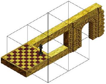
Figure 23. The structure in figure 22 transforms a vertical plane into a
horizontal one.
A note on the impossibility of IF
IF have been often called visual paradoxes, but the paradox lies more in our visual perception system than in the figures themselves. In fact, most IF are representations of totally possible objects. Take the Penrose tribar. Figure 24a shows a sculpture by Mathieu Hamaekers [1] that, in spite of some shadow clues, looks like an impossible triangle. But a shift in the point of view reveals the figure true nature - a triangular structure with curved limbs (fig. 24b). The paradox is that although we know a possible interpretation, this knowledge does not prevent us from perceiving a tribar as an IF.
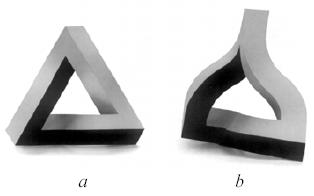
Figure 24. A sculpture by M. Hamaekers. a. Seen from the front. b.
Rotated 45 degrees.
Psychologists think the origin of the paradox lies in laws of thumb we acquire at early childhood in an effort to make sense of the world around us. We perceive a three dimensional world with our two dimensional retinas. When binocular vision is not involved - e.g. because the object is far away - we loose all stereo clues and must rely on ambiguous plane images. To make sense of data that are not univocal, we call in the rules of thumb.
One of the basic rules says we always make the more stable interpretation [8]. This means that, if we move the head a little and shift slightly the point of view, the interpretation of a figure we are looking at shall not change.
This rule explains all the "impossible" characteristics in the sets of tiles, except for the two points of view. For example, when we look at figure 25a we see the horizontal bar occluding the vertical one. We do not expect that, if me move our head a few centimetres up, we will find that the vertical bar has a gap that exactly matched the width of the horizontal bar (fig. 25b) in the previous view.
Figure 25. We perceive a as impossible because we do not expect to see b
when we move our head
Another result of the more stable interpretation law is that the tip of two lines meeting at a point must still meet when we shift the point of view. Hence, we interpret the points in the path meeting at figure 2a as actually meeting in space. A third consequence is that a straight line must remain straight when we move, a fact that explains why we do not see tribars and other IF as Hamaekers sculptures.
Conclusion
The set of impossible tiles provides an intuitive link between separate disciplines: design, mathematics and psychology. Traits that are usually treated by one of the disciplines are shown to be explained by another. It is the author’s hope the set can be used as a creative instrument, not only to produce known impossible structures but also to create new ones. The interested reader should make several enlarged copies of the sets and try her or his hand at them. If she or he prefers to use a PC program rather than manipulating actual tiles, there is a freeware version called Tritiles that can be downloaded through Internet [9].
Notes and references
- Ernst, B. (1986) Het gegoochelde oog, Landshoff, Utrecht. English translation: Optical Illusions, Taschen, Köln, 1992.
- Escher, M.C . (1967) The Graphic Work of M.C. Escher, Ballantine, New York
- Penrose, L. S. & R. (1958) Impossible Objects: A Special Case of Optical Illusions, British Journal of Psychology, 49, 31-33.
- Other interpretations are also available. For example, in figure 2a the left-hand branch of the horizontal bar can be seen as joining the vertical bar, with the left-hand branch running behind. Although this can easily be handled by drawing lines at the contours of the bars, it will result in a larger number of tiles.
- Uribe, D. (1978) Construcciones imposibles, La Revista del Snark, 8, 9, 10.
- Uribe, D. (1984) Construcciones imposibles, Cacumen, 18, 42-50.
- Mandelbrot, M. (1977) Fractals. Form, Chance and Dimension, W. H. Freeman & Co., San Francisco.
- Hoffman, D. D. (1998) Visual Intelligence, W. W. Norton & Co., New York.
- Tritiles was created by B. Cenk Gazen and M. Burçin Kermen and can be downloaded from www.cs.cmu.edu/~bcg/triangle/triangle.htm or from www.newmedia.kent.edu/eureka/Games/games.htm